
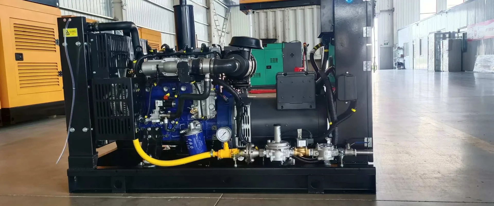
GAS PLANT ENGINEERING
Gas Treatment, Biogas Upgrading and Grid Integration
A Gas Genset Is Only Part of the Project
A gas generator set is the most visible item on a gas power project, and the least likely item to be the reason the project fails. What fails is the gas arriving at the engine in a condition the engine was not set up for, or the electricity leaving the alternator into a switchboard that cannot decide whether to island or parallel. Both are engineering scope that sits on either side of the set.
We quote gas plants as four linked packages rather than as a genset with accessories. The gas has to be conditioned before it reaches the mixer, the set has to be matched to that conditioned gas, the electrical interface has to be defined before the switchgear is built, and the heat has to be given somewhere to go. Getting the order of those four right is most of the engineering.
| Stage | What it does | What goes wrong if it is skipped |
|---|---|---|
| Gas supply and analysis | Establish composition, pressure, flow and variation through the day | The set is sized on a heat value the site does not actually have |
| Gas pretreatment | Filter, dry, regulate, temper and monitor the gas at the skid | Wet gas, pressure swings and dust reach the mixer and the valves |
| Genset and derating | Match compression ratio, mixer and rating to the conditioned gas | A nameplate rating that cannot be held at site conditions |
| Electrical interface | ATS, synchronising, load sharing, protection and earthing | The plant runs but cannot be paralleled, or trips on load steps |
Everything on this page is scope we can supply, specify or coordinate. Where a site already has a gas train or a switchboard, we engineer to what exists instead of insisting on our own package — the interface drawing is what matters, not the label on the panel.
Gas Pretreatment — Between the Pipe and the Engine
A gas engine is far less forgiving of its fuel than a diesel engine is of its fuel. Diesel arrives with a specification printed on it; gas arrives with whatever the well, the digester or the city main is delivering that week. Pretreatment exists to turn that variable stream into something the mixer, the regulator and the combustion chamber can work with continuously.
The train is built in stages, and each stage has a job that cannot be substituted by a more expensive filter. Drying does not remove sulphur, filtering does not remove water, and neither of them holds the outlet pressure steady when the upstream main dips.
| Module | Function | Design point we work to |
|---|---|---|
| Multi-stage particulate filtration | Removes dust, rust scale and pipe debris before the regulator | Particles down to 5 µm at the engine inlet |
| Multi-stage dehydration | Drops the dew point so liquid water cannot form at the mixer | No free liquid water at the lowest expected ambient |
| Pressure regulation | Holds a stable outlet pressure across the full load range | Outlet steady from no load to full load, with a relief path |
| Temperature conditioning | Keeps the gas inside the density window the mixer is calibrated for | Controlled inlet temperature range, not ambient-dependent |
| Online gas analysis | Tracks methane content and heat value as the source drifts | Continuous composition signal, logged |
| Heat-value-linked load control | Derates the set automatically when the gas weakens, instead of knocking | Load follows measured heat value, not a fixed assumption |
| Over-pressure and over-temperature protection | Multi-stage trips plus alarm, independent of the engine controller | Fail-safe shutoff, alarm to the plant SCADA |
The train is automated end to end. On a landfill or a digester site there is nobody standing next to the gas skid at three in the morning, so the control philosophy is unattended operation with remote alarm rather than a panel that needs a daily walk-round.
Gas Quality Limits the Engine Can Accept
These are the limits we design the fuel path against. They are not marketing figures — they are the point at which combustion stability, oil life or the exhaust after-treatment stops behaving predictably. A gas analysis that sits outside any one of them changes the specification of the set, not just the specification of the filter.
| Parameter | Limit | Consequence of exceeding it |
|---|---|---|
| Particulate matter | No free liquid water; particles below 5 µm | Valve seat erosion, cylinder liner wear, mixer fouling |
| Lower heating value | ≥ 5000 kcal/m³ (approx. 20.9 MJ/m³) | Output falls roughly in proportion; below the floor the set will not carry rated load |
| Sulphur content | ≤ 100 mg/m³ | Acid formation in the oil, corrosion of liners and bearings, shortened oil life |
| Methane content | > 30% for air-fuel ratio control | The lambda control window closes and combustion becomes unstable |
| Supply pressure at the skid | Stable band agreed at order, with margin above the mixer minimum | Load rejection or trip when the main dips; hunting at part load |
| Inlet temperature | Conditioned band, not raw ambient | Density change shifts the mixture and the derating |
Two practical notes. First, a heat value below the floor does not simply mean a smaller set — it means a different compression ratio and a different mixer, because the engine has to move more volume for the same energy. Second, altitude compounds everything: a set that holds rated load at sea level on 5000 kcal/m³ will not hold it at 2000 m on the same gas, and both deratings apply together.
Biogas Purification — Desulfurization, Compression, CO&sub2; Removal
Raw biogas from a digester or a landfill is typically 50–85% methane with carbon dioxide making up most of the balance, plus hydrogen sulphide as the main harmful trace component. Carbon dioxide costs you energy density and transport cost; hydrogen sulphide costs you the engine. The two are dealt with by different processes and should not be confused with each other.
Hydrogen sulphide is the one that decides oil change interval and overhaul life. It burns to sulphur dioxide, which meets condensate in the crankcase and forms acid. A digester running 3000–4000 ppm H₂S without desulphurization will destroy its oil long before its overhaul interval, and the damage shows up as liner and bearing corrosion rather than as a clean failure.
The standard sequence is desulphurization, then compression, then carbon dioxide removal. Dry or wet desulphurization upstream of compression is preferred because it removes the H₂S before it can wet the compressor internals, and because it loses almost no methane. Pressure swing adsorption for CO&sub2; removal recovers better than 95% of the methane in the feed, and the product gas is brought to the quality defined in GB 17820-2012 for pipeline-grade natural gas where the site needs that grade.
| Route | What is removed | Where it fits |
|---|---|---|
| Desulphurization only | H₂S, with filtration and drying | On-site engine fuel where the gas stays on the site and pipeline grade is not required |
| Desulphurization + compression | H₂S, water, pressure raised for transport or storage | Gas fed to a distant engine, or to a holder that needs pressure |
| Full upgrading: desulphurization + compression + PSA CO&sub2; removal | H₂S, water, CO&sub2;, to pipeline or vehicle-fuel grade | Biomethane injection, CNG production, or a plant that wants maximum energy per cubic metre |
Purification is sized from the gas analysis, not from the digester nameplate. Two digesters of the same volume can deliver very different H₂S loads depending on feedstock, and the desulphurization bed is what you run out of first. We size the bed on the measured load plus margin, and we instrument the outlet so the change-out is planned rather than discovered.
Parallel Operation, Island Mode and Grid Connection
How the plant connects decides the switchgear, the controller, the protection and the earthing. It is a decision to make at order, not at commissioning, because a set built for standby duty does not become a paralleling set by adding a cable.
| Mode | Switchgear required | Protection that must be set |
|---|---|---|
| Standby, single set | ATS between mains and set | Overcurrent, earth fault, under/over voltage and frequency, fail-to-start |
| Single set paralleled to grid | Synchronising breaker plus grid-protection relay | Reverse power, overcurrent, loss of mains, over/under voltage and frequency, load rejection |
| Multi-set parallel, island or grid | Paralleling panel with digital load sharing, plus grid interface where applicable | All of the above plus set-level load imbalance, circulating current and master/slave failure handling |
Automatic synchronising. The synchronising panel brings the incoming set to matching voltage, frequency and phase angle before closing, so the breaker closes on a small or zero vector difference. Doing this by hand is possible and is how plants were run for decades, but on a site with several sets and varying load, automatic synchronising is what makes unattended operation realistic.
Load sharing and load-dependent start. On a multi-set plant the controller decides how many sets run. Below a threshold, running three sets at 30% each burns more fuel than running one at 90%. The panel starts sets as load rises and stops them as it falls, with hysteresis so it does not cycle. This is where most of the fuel saving in a multi-set plant actually comes from — not from the engine efficiency curve.
Island mode. An islanded plant has to define what happens when load falls below the minimum stable output of the smallest running set. Either the set goes to a load bank, or the plant accepts a lower efficiency band, or the control scheme defines a minimum set count. Leaving it undefined is how a plant ends up with a set that hunts and trips at night.
ATS, Switchgear and Load Transfer
The automatic transfer switch is the smallest item on the electrical side and the one most often bought on price alone. It is also the item that has to break a fault current it did not create, and to be serviceable by someone who has never seen the panel before.
The configuration we specify has three positions — mains, off, generator — with a mechanical interlock so both sources can never be closed together, and a visible break at the off position so an electrician can confirm isolation without trusting a lamp. Emergency manual operation is provided so the plant is not stranded if the control supply fails.
| Frame size | Typical genset match (400 V) | Typical genset match (10.5 kV, via breaker) |
|---|---|---|
| 100–250 A | Up to approx. 140 kVA | — |
| 400–630 A | Approx. 250–400 kVA | Vacuum breaker at set voltage |
| 800–1250 A | Approx. 500–800 kVA | Vacuum breaker at set voltage |
| 1600–2000 A | Approx. 1000–1250 kVA | Vacuum breaker at set voltage |
| 2500–3200 A | Approx. 1600–2000 kVA | Vacuum breaker at set voltage |
The ratings above are indicative frame classes, not a selection table. Final selection depends on the calculated fault level at the point of connection, the cable and busbar impedance upstream, and whether the ATS is required to be rated for the full generator fault contribution — which on a paralleled plant is the sum of every set on the bus.
Load transfer timing. Transfer time matters differently for different loads. A lighting and socket load tolerates a two-second break; a chiller plant may not, and a data hall almost certainly will not. Where transfer time is critical, the answer is usually a UPS or a flywheel on the critical bus rather than a faster ATS, because the mechanical switch is not the limiting factor.
Heat Recovery and CHP Readiness
A gas engine converts roughly 40–46% of its fuel energy into electricity. Most of the remainder leaves as exhaust heat and jacket water heat. On a plant that runs thousands of hours a year, that heat is the difference between a 42% efficient installation and an 85–90% efficient one, and it is recovered with equipment that is designed alongside the set rather than added afterwards.
Two heat streams are available. Jacket water is low grade and steady, typically available at 80–95 °C, and suits hot water, space heating or digester warming. Exhaust gas is high grade and variable with load, and suits steam, drying or absorption chilling. Recovering both at once is normal; recovering exhaust alone is the common shortcut that leaves most of the low-grade heat on the table.
| Output class | Electrical output | Electrical efficiency | Thermal output | Total efficiency |
|---|---|---|---|---|
| 330 kW class | 330 kW | 38.8% | 371 kW | 82.4% |
| 640 kW class | 635 kW | 40.8% | 739 kW | 88.2% |
| 850 kW class | 851 kW | 40.7% | 991 kW | 88.0% |
| 1.07 MW class | 1067 kW | 40.9% | 1241 kW | 88.5% |
| 1.50 MW class | 1501 kW | 43.0% | 1563 kW | 87.8% |
| 2.00 MW class | 2004 kW | 45.0% | 1930 kW | 88.3% |
| 3.36 MW class | 3360 kW | 45.6% | 3172 kW | 88.6% |
| 4.50 MW class | 4500 kW | 46.4% | 4230 kW | 90.0% |
Figures are reference values for the output class on natural gas, at 50 Hz, ISO conditions, with both jacket water and exhaust heat recovered. Biogas figures sit lower on the thermal side — typically 85–86% total efficiency on the same class — because the lower methane content reduces the exhaust energy available per kWh generated. Always quote against the gas analysis for the actual site.
Above the 1 MW class we integrate international-brand gas gensets — the Jenbacher Type 2, 3, 4 and 6 ranges and the Cummins gas series — where the site needs that output, with the balance of plant, heat recovery and electrical interface engineered by us. Below that class, our own JJP-G range covers 16–900 kW.
Scope of Supply
Gas plants go wrong at the interfaces. One supplier provides the gas train, another the set, a third the switchgear, and nobody owns the drawing where they meet. We would rather define the battery limit in writing before the order than argue about it during commissioning.
| Package | Included | Typical client scope |
|---|---|---|
| Gas treatment | Filtration, drying, regulation, temperature control, analysis, protection skid | Gas supply to the skid inlet flange, civil base, power and signal to the plant network |
| Biogas upgrading | Desulphurization, compression, PSA CO&sub2; removal, online monitoring | Raw gas delivery, product gas offtake, utilities |
| Genset | Engine, alternator, control panel, baseframe, couplings, ancillaries | Foundation, enclosure or building, exhaust route |
| Electrical interface | ATS, synchronising panel, paralleling panel, protection relays, load sharing | Incoming cable, earthing grid, transformer where the set is at a different voltage |
| Heat recovery | Exhaust heat exchanger, jacket water circuit, bypass, control valves | Heat distribution network, end-use equipment |
| Acoustic and emission | Enclosure, silencer, SCR where required, room treatment design | Building works, reagent supply and storage |
| Services | Drawings, commissioning, performance test, operator training, spares list | Site access, utilities during commissioning, operating staff |
Project Sequence — Gas Analysis to Commissioning
The sequence below is the order that keeps the interfaces from being re-opened later. Most of the cost of a badly run gas project is not in the equipment; it is in redoing switchgear because the operating mode changed after the order, or in replacing a mixer because the gas analysis arrived after the set was built.
| Step | Activity | Output that must be signed off |
|---|---|---|
| 1 | Gas analysis and site survey | Composition, heat value, H₂S, pressure, flow, ambient, altitude |
| 2 | Rating and derating calculation | Guaranteed output at site conditions, not nameplate |
| 3 | Operating mode definition | Standby, island, parallel or export; single or multi-set |
| 4 | Gas train and electrical design | P&ID, single-line diagram, interface schedule, battery limits |
| 5 | Manufacture and factory test | Set test record, panel function test, witness test where specified |
| 6 | Installation and mechanical completion | Alignment, pipework pressure test, cable terminations, earthing test |
| 7 | Commissioning and performance test | Load test, emissions test, noise measurement, protection trip test, handover |
Step 1 is the one clients most often want to skip because the gas analysis costs money and takes time. It is also the only step that cannot be recovered later without changing hardware. A composition report and a week of pressure logging will save more than they cost on almost every project.
Frequently Asked Questions
Do I need gas pretreatment if my gas is pipeline natural gas?
Usually a reduced train rather than none. Pipeline gas is already dry and filtered to a utility standard, but the pressure at the site still varies, and the regulator at the set needs a stable inlet. Most pipeline installations need pressure regulation and a final filter, not full dehydration.
How much does gas quality actually reduce output?
Roughly in proportion to the heat value delivered, once the set is at its calibrated point. A gas at 4000 kcal/m³ against a 5000 kcal/m³ design point gives around 80% of rated output, before altitude correction. Below about 30% methane the air-fuel ratio control stops being able to hold a stable mixture at all.
Can I add paralleling later?
Adding a second set later is normal and the panel can be built with spare ways for it. Converting a standby set into a paralleling set is not a panel change — it needs a different breaker, a different controller and a different earthing arrangement, and on most sets it is cheaper to specify it at order.
What H₂S level makes desulphurization necessary?
Any sustained level above roughly 100 mg/m³ shortens oil life measurably, and digester gas is routinely an order of magnitude above that. Practically, if the gas is from a digester or a landfill, plan for desulphurization from the start rather than waiting for the first oil analysis to tell you.
Is PSA the only way to remove CO&sub2;?
No. Water scrubbing, amine absorption and membrane separation are all used commercially. PSA recovers over 95% of the methane with no chemical consumption and modest footprint, which is why it dominates on mid-size plants. The right choice depends on the target gas grade, the utilities available and the turndown the plant needs.
How much heat can I actually recover?
On a well-designed installation, total efficiency of 85–90% is achievable on natural gas, with roughly half the recovered heat from jacket water and half from exhaust. The limit is usually the heat load on the site, not the engine — a plant with no year-round heat demand should not pay for a heat recovery package it will bypass.
What is the largest gas plant you can supply?
Our own JJP-G range covers 16–900 kW. Above that we integrate international-brand gas gensets in the 1–4.5 MW class and engineer the balance of plant — gas treatment, heat recovery, switchgear and control — around them, with multi-set plants running into tens of megawatts.
What information do you need to quote a gas plant?
The gas analysis or at least the gas type and source, the required electrical output, the operating mode, the site voltage, the altitude and ambient range, whether heat recovery is wanted, and the emission or noise limits the site has to meet. With those we can fix the model, the derating and the scope rather than quote a range.
GET YOUR GENERATOR SOLUTION TODAY
Contact us now for free consultation, custom quotes, and technical support. Factory-direct pricing with global shipping.