86-0769-89610677 / 86-13553838770 | info@jinjiadongli.com
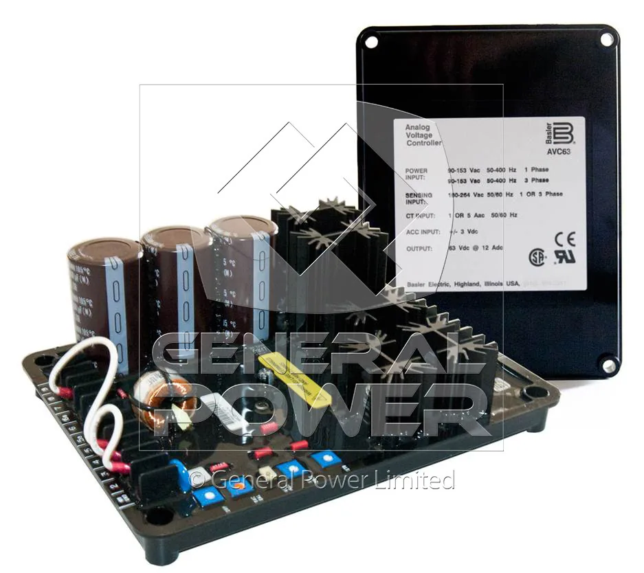
Status: IN STOCK, Same day shipping Worldwide available | Brand New, 1 Year International Warranty
* Contact us for pricing and full specifications
| SKU | AVC63-12B1 |
| Brand | BASLER |
| Model Number | AVC63-12B1 |
| Regulator Type | Analogue Automatic Voltage Regulator |
| Excitation System | Self-excited, shunt or auxiliary-winding fed |
| Sensing Input | Single-phase, 120 V / 240 V class |
| Power Input | Single-phase, 50 / 60 Hz |
| Output Voltage | 63 Vdc class |
| Continuous Field Current | 12 Adc continuous |
| Forcing Current | 24 Adc for 10 s |
| Field Resistance (Min) | 10 ohm minimum |
| Regulation Accuracy | +/-1.0 per cent |
| Response Time | About 20 ms |
| Frequency Range | 50 / 60 Hz |
| Under-Frequency Protection | Volts-per-hertz roll-off |
| Voltage Adjustment | Internal trim potentiometer |
| Paralleling / Droop | Reactive droop via CT |
| Build-Up Voltage | Builds up from residual voltage |
| Thermal Drift | 0.05 per cent per degC |
| Operating Temperature | -40 to +60 degC |
| Storage Temperature | -40 to +85 degC |
| Protection Features | Over-excitation shutdown, integral fuse |
| Compatible Alternators | Alternators 800-1500 kVA |
| Mounting | Panel mount with standard screw terminals |
| Lifecycle Status | In production |
| Availability | IN STOCK, Same day shipping Worldwide available |
| Condition | Brand New, 1 Year International Warranty |
| Warranty | 1 Year International Warranty |
Position in the range. The AVC63-12B1 sits in the BASLER regulator family carrying the designation Analogue Automatic Voltage Regulator. Its place is defined by the field current it can hold, 12 Adc continuous, against the field resistance it can drive, 10 ohm, at +/-1.0 per cent accuracy over -40 to +60 degC. Where a machine falls outside either of the first two figures, a different member of the same family is the correct answer rather than a workaround.
Excitation architecture. Self-excited, shunt or auxiliary-winding fed. That single sentence decides most of the regulator's behaviour in a fault: whether the field survives a close-up short circuit, whether the machine builds up from residual voltage on its own, and how much the terminal voltage dips when a large motor starts on the same bus. Counterfeit regulators are a real problem on the widely copied boards. Buy from a source that will state where the board was made.
Sensing. Single-phase, 120 V / 240 V class. The sensing circuit is the regulator's only view of the outside world, so its wiring matters as much as its specification. A voltage error introduced by a loose terminal or a long run of untwisted cable is indistinguishable, from the regulator's point of view, from a genuine voltage error on the alternator. A regulator rated for a minimum field resistance of a few ohms will not drive a high resistance field to full current, however good its specification looks on paper.
Power stage and field drive. Power input Single-phase, 50 / 60 Hz, output 63 Vdc class. Field current rating 12 Adc continuous, forcing capability 24 Adc for 10 s, field resistance window 10 ohm. These are not independent numbers: the output voltage ceiling and the field resistance together set the maximum current the board can actually deliver, and the continuous rating is only reachable at the low end of the resistance window. Load sharing between parallel sets is set up with an instrument, not by ear. A droop adjustment made by listening to the sets will be wrong at every load other than the one it was set at.
Accuracy and response. +/-1.0 per cent steady-state accuracy, About 20 ms, thermal drift 0.05 per cent per degC. In practice the accuracy figure is the least interesting of the three. What an operator notices is recovery after a load step, which is governed by response and by available forcing current, and what a maintenance engineer notices after two years is drift, which is governed by the reference circuit and the ambient temperature inside the terminal box. The measurement that settles most arguments is the field current at full load, taken with a clamp meter, compared against the rating on the board.
Frequency behaviour. Rated for 50 / 60 Hz, with Volts-per-hertz roll-off. The frequency-sensitive function exists to protect the prime mover, not the alternator: as engine speed falls the regulator reduces excitation so the alternator stops demanding torque the engine cannot supply. Without it, an overloaded engine is dragged down until it stalls, and the alternator is blamed for a fault that belongs to the fuel or governor system. Load sharing between parallel sets is set up with an instrument, not by ear. A droop adjustment made by listening to the sets will be wrong at every load other than the one it was set at.
Paralleling. Reactive droop via CT. On a single set this circuit does nothing. On two or more sets it is the only thing that stops the machines from exchanging reactive power in a slow oscillation, and it is the first place to look when a parallel installation shows a circulating current that nobody can explain. Terminal boxes are hot, dirty and vibrating. Anything mounted inside one should be judged on how it behaves in year eight, not on how it reads on the bench.
Protection built into the regulator. Over-excitation shutdown, integral fuse. These functions protect the alternator and the regulator, not the installation. Downstream protection, loss of mains and reverse power all belong to the controller, and a site that relies on the AVR for them is a site that will eventually trip in a way nobody can explain. A regulator rated for a minimum field resistance of a few ohms will not drive a high resistance field to full current, however good its specification looks on paper.
What it fits. Alternators 800-1500 kVA. Lifecycle status: In production. Both halves of that sentence matter at order time. A board that fits perfectly but has been discontinued is a different commercial decision from one that fits and is in current production, and the price difference rarely reflects the difference in risk. The trim potentiometer is not a calibration device. If rated voltage is not reachable near the middle of its range, the sensing tap is wrong.
Field notes on this model. The AVC63-12 is the largest analogue member of the Basler AVC63 line. It is chosen when the exciter field needs more than 7 A standing current, typically on large frame alternators above 800 kVA, and it keeps the analogue simplicity that makes it serviceable on site without a laptop.
Matching the board to the duty, not to the label. Two BASLER alternators of the same kVA can need different regulators if one is specified for motor starting and the other for a resistive load. The AVC63-12B1 is specified at +/-1.0 per cent regulation accuracy, which is the number that matters when the load is a mix of drives and lighting. For a purely resistive load even a looser board is invisible to the customer, and paying for accuracy that nobody measures is the most common way money is wasted on a rebuild.
Earthing and shielding. The regulator reference is the machine frame. Bond the AVR mounting plate to the frame with a dedicated conductor rather than relying on the mounting screws, and earth the sensing cable shield at one end only. When a set shows a voltage that wanders slowly with no load change, the cause is usually a circulating current in the shield rather than a failing board.
Paralleling setup. With two sets on the bus, adjust droop until reactive load divides in proportion to machine rating, then check it again at half load. A droop setting that looks right at full load and wrong at half load is usually a CT ratio error rather than a regulator fault.
Series resistance is not a fix. Adding a resistor in series with the field to bring it inside a regulator window costs forcing current exactly when the machine needs it most. If the field resistance is outside the window, change the board, not the circuit.
Hunting or slow oscillation. Oscillation at one to three seconds period is a stability setting problem. Oscillation at a fraction of a second is usually a sensing problem, often a bad connection that makes the reference jump. Distinguishing between the two by ear is possible and saves a lot of time.
Part numbers are not interchangeable across suffixes. On this family the suffix carries the field current class, the sensing arrangement or the frequency band, and two boards that look identical in a photograph can be a hundred per cent different in rating. Quote the full model number including the suffix, and where the suffix is unclear send a photograph of the original board with the terminal markings visible.
Reading the application backwards. Most regulator problems arrive described as engine trouble. A set that hunts on load, or whose voltage sags for two seconds after a contactor closes, is usually reporting a field current limit rather than a fuel problem. On a AVC63-12B1 the first thing to check is whether the 12 Adc continuous figure is being reached on a cold morning, because field resistance rises with temperature in the opposite direction to copper and a board that is marginal at 20 degC can be comfortable at 50 degC or the other way round depending on the winding.
Documentation that survives the job. Photograph the terminal block before disconnecting anything, and write the sensing tap and the field resistance on the inside of the terminal box lid. Ten years later that note is the only thing that will let the next engineer choose a replacement without a full survey.
Jinjia Power Equipment Co., Ltd | Address: No.737, Guanzhang Road, Liaobu Town, Dongguan, China
Phone: 86-13553838770 | 86-0769-89610677 | info@jinjiadongli.com
Jinjia Power, Quality Assured