86-0769-89610677 / 86-13553838770 | info@jinjiadongli.com

Status: IN STOCK, Same day shipping Worldwide available | Brand New, 1 Year International Warranty
* Contact us for pricing and full specifications
| SKU | M71FA310 |
| Brand | MARELLI |
| Model Number | M71FA310 |
| Regulator Type | Analogue Automatic Voltage Regulator, Mark X platform |
| Excitation System | PMG fed, designed for Marelli MJB alternators with a permanent magnet pilot exciter |
| Sensing Input | Single-phase, 170-480 Vac, 50 / 60 Hz, +/-10 per cent tolerance |
| Power Input | Auxiliary winding or main terminals, 170-277 Vac at 100 / 120 Hz, +/-10 per cent |
| Output Voltage | 100 Vdc maximum |
| Continuous Field Current | 8 Adc continuous |
| Forcing Current | 15 Adc for 1 minute |
| Field Resistance (Min) | 3-20 ohm, or 3.5-20 ohm on some builds |
| Regulation Accuracy | +/-0.5 per cent from no load to full load at 0.8 power factor on balanced undistorted load at constant frequency. Steady-state accuracy +/-0.1 per cent, or +/-1 per cent with 4 per cent engine governing |
| Response Time | One cycle |
| Frequency Range | 50 / 60 Hz |
| Under-Frequency Protection | Under-frequency limiter with an adjustable knee |
| Voltage Adjustment | A 100 kohm external potentiometer gives +/-5 per cent of rated voltage, and an external DC signal of -3 / +3 V suits a power factor controller |
| Paralleling / Droop | Reactive droop compensation, +/-20 per cent |
| Build-Up Voltage | Builds up from 5 Vac residual |
| Thermal Drift | +/-0.5 per cent for a 50 degC ambient change after a 10 minute warm-up |
| Operating Temperature | -30 to +70 degC |
| Storage Temperature | -40 to +80 degC |
| Protection Features | Under-frequency limiter, over-excitation limiter, internally replaceable fuse |
| Compatible Alternators | Marelli MJB 225-500 frame alternators |
| Mounting | Panel or terminal-box mount |
| Lifecycle Status | In production |
| Availability | IN STOCK, Same day shipping Worldwide available |
| Condition | Brand New, 1 Year International Warranty |
| Warranty | 1 Year International Warranty |
What the M71FA310 is. A Analogue Automatic Voltage Regulator, Mark X platform built by MARELLI for brushless excitation systems. On paper the specification is a list; in service it is a set of limits. The current the board will hold indefinitely is 8 Adc continuous; the field resistance window it will drive without exceeding its output voltage is 3-20 ohm; the tightest voltage band it can maintain is +/-0.5 per cent; and the ambient range in which all of that remains true is -30 to +70 degC.
Excitation architecture. PMG fed, designed for Marelli MJB alternators with a permanent magnet pilot exciter. That single sentence decides most of the regulator's behaviour in a fault: whether the field survives a close-up short circuit, whether the machine builds up from residual voltage on its own, and how much the terminal voltage dips when a large motor starts on the same bus. A regulator rated for a minimum field resistance of a few ohms will not drive a high resistance field to full current, however good its specification looks on paper.
Sensing. Single-phase, 170-480 Vac, 50 / 60 Hz, +/-10 per cent tolerance. The sensing circuit is the regulator's only view of the outside world, so its wiring matters as much as its specification. A voltage error introduced by a loose terminal or a long run of untwisted cable is indistinguishable, from the regulator's point of view, from a genuine voltage error on the alternator. Conformal coating is the difference between a board that survives a coastal site and one that corrodes quietly in eighteen months.
Power stage and field drive. Power input Auxiliary winding or main terminals, 170-277 Vac at 100 / 120 Hz, +/-10 per cent, output 100 Vdc maximum. Field current rating 8 Adc continuous, forcing capability 15 Adc for 1 minute, field resistance window 3-20 ohm. These are not independent numbers: the output voltage ceiling and the field resistance together set the maximum current the board can actually deliver, and the continuous rating is only reachable at the low end of the resistance window. Field resistance is a temperature-dependent number. A reading taken on a cold morning and a reading taken after an hour at load are both correct and both different.
Accuracy and response. +/-0.5 per cent steady-state accuracy, One cycle, thermal drift +/-0.5 per cent for a 50 degC ambient change after a 10 minute warm-up. In practice the accuracy figure is the least interesting of the three. What an operator notices is recovery after a load step, which is governed by response and by available forcing current, and what a maintenance engineer notices after two years is drift, which is governed by the reference circuit and the ambient temperature inside the terminal box. An alternator that has been rewound needs its field resistance re-measured, because a rewind commonly moves it by ten to twenty per cent in either direction.
Frequency behaviour. Rated for 50 / 60 Hz, with Under-frequency limiter with an adjustable knee. The frequency-sensitive function exists to protect the prime mover, not the alternator: as engine speed falls the regulator reduces excitation so the alternator stops demanding torque the engine cannot supply. Without it, an overloaded engine is dragged down until it stalls, and the alternator is blamed for a fault that belongs to the fuel or governor system. The cheapest diagnostic tool in excitation work is a DC ammeter in the field circuit. It turns a vague symptom into a number within seconds.
Paralleling. Reactive droop compensation, +/-20 per cent. On a single set this circuit does nothing. On two or more sets it is the only thing that stops the machines from exchanging reactive power in a slow oscillation, and it is the first place to look when a parallel installation shows a circulating current that nobody can explain. A set that runs at reduced speed will show low voltage on any regulator. Check engine speed against the nameplate before touching the excitation system.
Protection built into the regulator. Under-frequency limiter, over-excitation limiter, internally replaceable fuse. These functions protect the alternator and the regulator, not the installation. Downstream protection, loss of mains and reverse power all belong to the controller, and a site that relies on the AVR for them is a site that will eventually trip in a way nobody can explain. Where a spare is being held, hold the drawing with it. A board without its wiring diagram costs a shift of production time to install.
What it fits. Marelli MJB 225-500 frame alternators. Lifecycle status: In production. Both halves of that sentence matter at order time. A board that fits perfectly but has been discontinued is a different commercial decision from one that fits and is in current production, and the price difference rarely reflects the difference in risk. On a machine that has been standing for months, check residual voltage before condemning anything: a winding that has lost its remanence will not build up on any regulator.
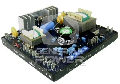
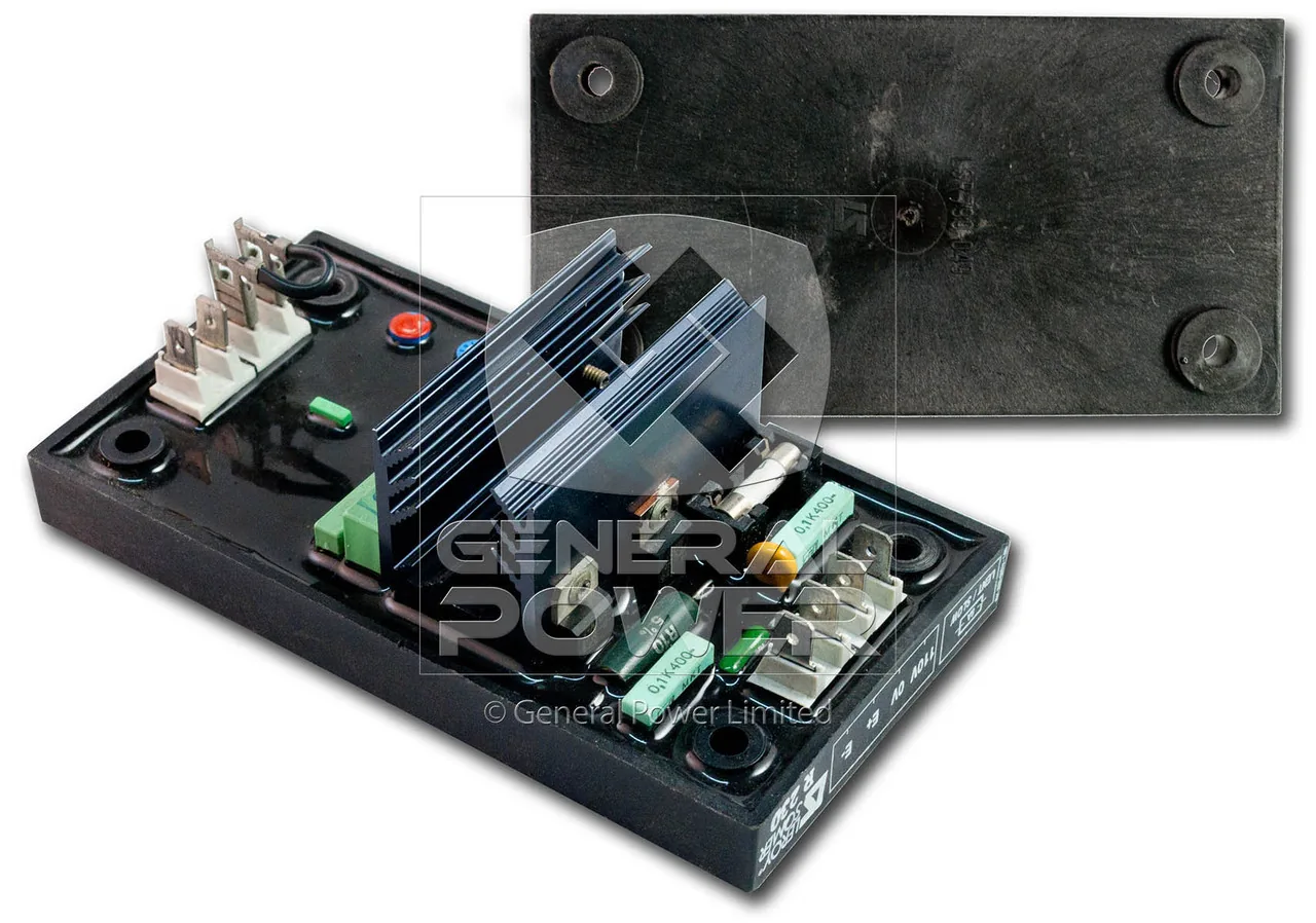
Field notes on this model. The Mark X is fully resin-encapsulated, which is what makes it survive humidity, conductive dust, salt spray and the vibration of a marine or offshore installation. It is designed around a PMG, so excitation holds up through a short circuit. Marelli also publishes the external control interface: a 100 kohm potentiometer gives +/-5 per cent voltage trim, and a -3 / +3 V DC signal lets a power factor controller drive it directly.
Reading the application backwards. Most regulator problems arrive described as engine trouble. A set that hunts on load, or whose voltage sags for two seconds after a contactor closes, is usually reporting a field current limit rather than a fuel problem. On a M71FA310 the first thing to check is whether the 8 Adc continuous figure is being reached on a cold morning, because field resistance rises with temperature in the opposite direction to copper and a board that is marginal at 20 degC can be comfortable at 50 degC or the other way round depending on the winding.
The terminal box is a hostile place. Engine vibration, radiant heat from the exhaust and conductive dust all arrive at the same panel. Mount the M71FA310 on the resilient side of the box if there is a choice, keep it off the hottest wall, and make sure the lid actually closes over the wiring rather than pinching it. A regulator that is mechanically stressed will eventually crack a solder joint, and the resulting fault looks exactly like a failed semiconductor.
What to record. Write down the sensing tap used, the field resistance cold, the field current at no load and at full load, and the voltage trim position. Those four numbers turn the next service visit from an investigation into a comparison.
Rewind caution. After a field rewind the resistance often changes by ten to twenty per cent, which can push a marginal regulator out of range. Whenever a machine comes back from a rewind, re-check the regulator against the new field resistance before returning it to service.
Voltage low under load only. This is the classic field current limit symptom. Measure the field current at full load and compare it with the 8 Adc continuous figure for the M71FA310. If the board is at its limit, either the board is too small for the alternator or the field resistance has risen. A rewind, a corroded terminal or a long cable run will all produce the same reading.
Warranty and what it covers. A one year warranty on a regulator is meaningful only if it covers a field-side failure and not just a dead-on-arrival check. Ask whether a board that fails after six months in service is replaced without argument, because that is the failure mode that actually happens.
Parallel operation is a different animal. A single set on an island load only has to hold voltage. Two sets in parallel also have to agree about reactive load, and that agreement is made or broken by the droop circuit, not by the voltage accuracy. If a site is going to parallel, the regulator choice has to be made with the droop method in mind from the beginning, because retrofitting load sharing onto a board that was never specified for it costs more than buying the right one.
Field cable sizing. The field circuit carries DC at low voltage and high current, so volt drop matters more than ampacity. Size the cable so that the drop at 8 Adc continuous stays under about one volt, and torque the terminals to the manufacturer figure. A field circuit that loses half a volt in the cable is a regulator that cannot reach full forcing when the load steps.
Jinjia Power Equipment Co., Ltd | Address: No.737, Guanzhang Road, Liaobu Town, Dongguan, China
Phone: 86-13553838770 | 86-0769-89610677 | info@jinjiadongli.com
Jinjia Power, Quality Assured